Inputs and outputs
The number of inputs and outputs depends on the RTU-X model (IP68 or DIN) and on the use of expansion modules.
All configuration related to inputs and outputs is done in the I/O section of the user interface.
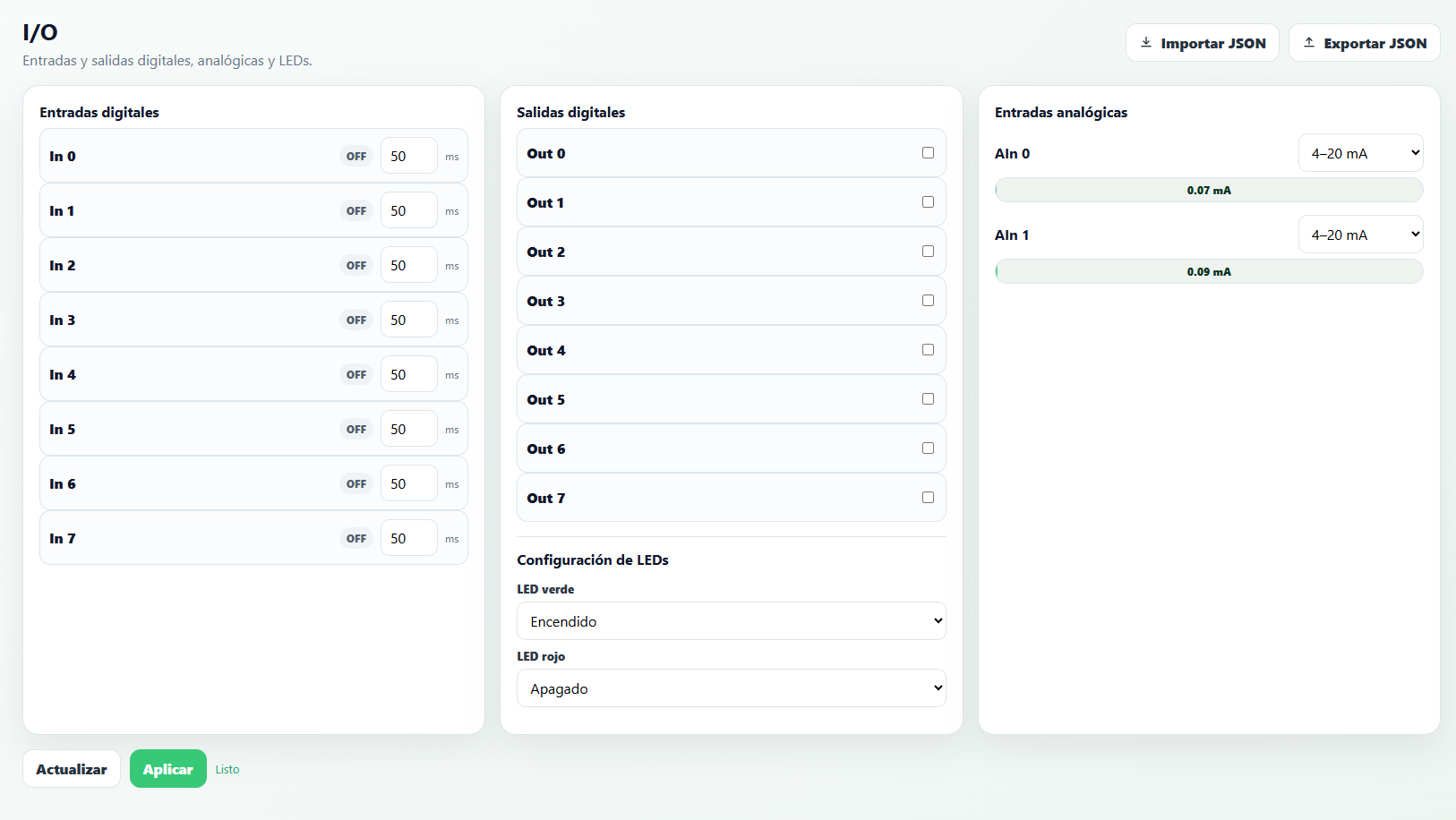
Digital inputs
The IP68 model has a base of 2 digital inputs, while the DIN model has a base of 8 digital inputs.
The inputs are dry contact. To activate one, the input must be forced to GND. Each input also has a debounce field (in ms) to filter contact noise.
Digital inputs can be read from the script with the get_input function and can also be viewed in the I/O section.
Using extension modules, you can add conventional digital outputs or pulse differential outputs for controlling latching solenoid valves. When an output extension module is installed on the device, the outputs corresponding to that module appear in the user interface and can be triggered manually or from a script.
Pulse counter
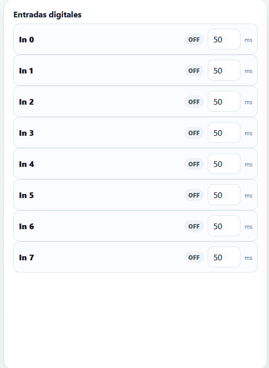
In both models, the IN0 and IN1 inputs can be used to count pulses, even when the device is in low power mode.
The RTU-X implements a noise filter in the pulse count: it's the same debounce field (in ms) that appears next to each digital input in the screenshot from the previous section — there's no separate screen for the pulse counter, it's configured from there.
The pulse count for each input can be read from the script in the pulses[] array.
Digital outputs
The IP68 model has a base of 1 digital output, while the DIN model has a base of 8 digital outputs.
The digital outputs are optoisolated, supporting a maximum voltage of 300V and a maximum current of 100mA.
Digital outputs can be read and modified from the script with the get_output and set_output functions. They can also be viewed and modified in the I/O section.
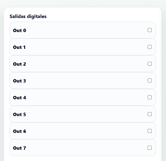
When digital output extension modules are installed, additional outputs are added to the base outputs (which depend on the model): extension module 1 adds outputs 8, 9, and 10; extension module 2 adds outputs 11, 12, and 13.
Analog inputs
Both RTU-X models have a base of 2 analog inputs with 12-bit resolution, which can each be configured independently to work as current (0-20mA) or voltage (0-10V) inputs.
The number of analog inputs can be increased with the AIN expansion module, which adds 3 analog inputs per module with characteristics identical to the 2 base analog inputs.
The operating mode of each analog input is configured in the I/O section, which also shows the real-time measured value.
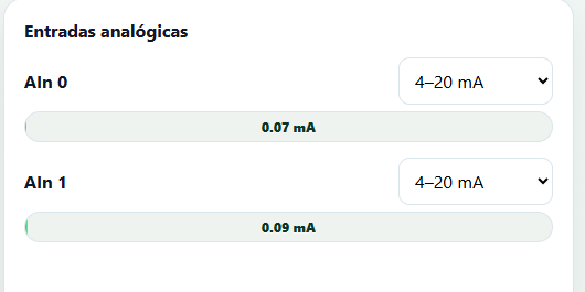
Analog inputs can be read from the script with the ain[] variable. The value is expressed in mV when the input is voltage, and in uA when the input is current.
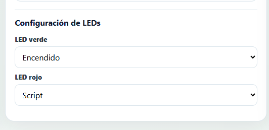
LEDs configuration
The RTU-X has two LEDs, one green and one red, which can each be configured independently and flexibly to give a visual indication of the operating status of the device's different modules.
The possible states for each LED are:
- Off – Always off.
- On – Always on.
- Fast blink – 100ms on, 100ms off.
- Slow blink – 1 second on, 1 second off.
- Blip – Short flash. 100ms on, 1.5 seconds off.
Each LED can be configured to work in one of the following ways:
- Off — Always off.
- On — Always on.
- WiFi — Reflects the state of the WiFi connection.
- Off – WiFi disconnected.
- Fast blink – WiFi connecting.
- Blip – WiFi connected.
- Modem — Reflects the modem's operating status.
- Off – Modem off.
- Fast blink – Modem powering on.
- Blip – Modem working correctly.
- On – Error (use the user interface to determine the error).
- MQTT — Reflects the state of the MQTT connection.
- Off – Not connected.
- Fast blink – Connecting.
- Blip – Connected.
- Script — Lets you control the behavior of each LED dynamically from the script, using the
set_green_ledandset_red_ledfunctions.
12V/24V Output
The RTU-X has an output for powering external sensors, which can be configured to generate 12 VDC or 24 VDC, with a capacity of up to 12W of power.
To control the output, use the set_power function as follows:
set_power(POWER_OFF); // Disables the output
set_power(POWER_12V); // Enables the output at 12V
set_power(POWER_24V); // Enables the output at 24V
When the RTU-X goes into low power mode (sleep), this output's state is preserved. To minimize consumption, the output must be turned off (set_power(POWER_OFF)) before calling the sleep function.
Buttons
Both RTU-X models have two buttons:
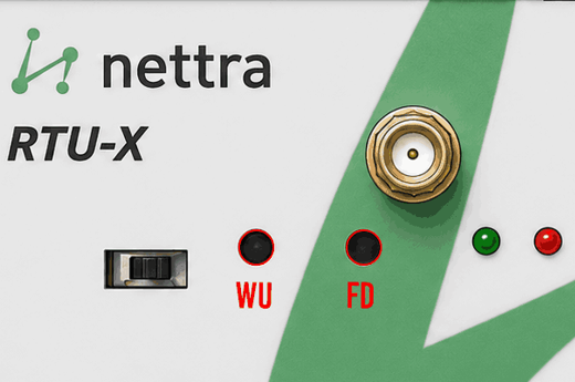
DIN model
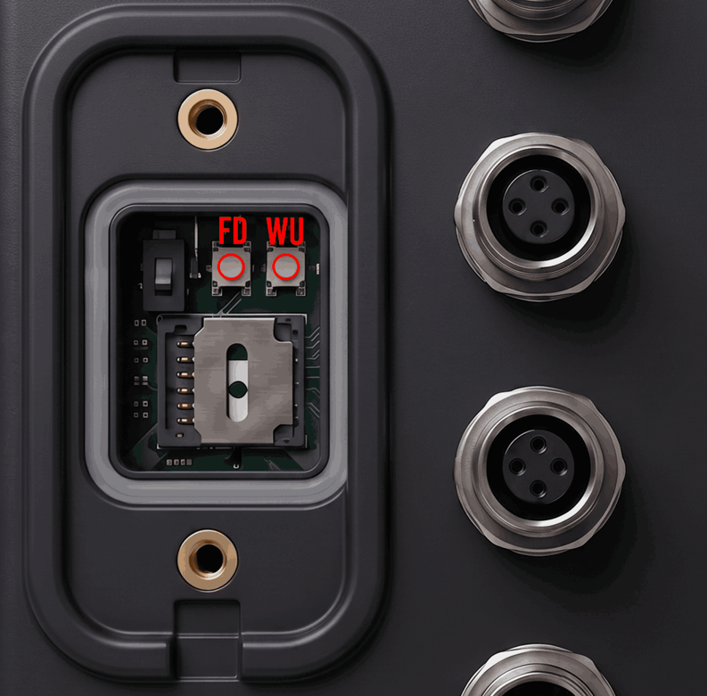
IP68 model
Factory default
Holding this button pressed for more than 3 seconds makes the RTU-X erase its configuration (but keeps the firmware version currently loaded). If held pressed for more than 10 seconds, or if the device is powered on with this button pressed (removing external power and the battery), in addition to erasing the configuration the device also reverts to its factory firmware.
No matter how many times the device's firmware is updated, the original factory version is always kept saved, so it's always possible to roll back to the original version in case of failure.
Wake up
When the device is asleep after executing the sleep() statement in the script, pressing this button wakes the device up and stops the script's execution. When the device is awake, this button's state is accessible from the script through the button system variable.